Friday, February 9, 2024
Permanente II
Permanente II
Magnesium Technology Built on American Know-How
Including Carbothermal Technologies for:
(Li, Zn, Ca, Cd, etc.)
2024 Version
Presented with the hope that this information will contribute to the reshoring of the metals industry in America.
Where is the Henry Kaiser of the 21st Century?
A futuristic Permanente II process for magnesium production; image created by AI.
Table of Contents
Basics of Carbothermal Magnesium Production 5
Where My Life Intersected with Magnesium 5
A Closer Look at the Permanente Process 6
The Laval Nozzle and the Carbothermal Process 8
Figure 1. The Laval (Lavalle) Nozzle 8
Introducing an Ejector (Eductor) Nozzle and a Few Other Important Changes 11
Figure 2. Eductor/Ejector Nozzle 12
Disadvantages of the Ejector 12
Advantages of an Ejector System 13
Figure 3. Permanente II Core Technology 14
Beyond the Basics with Carbo-Thermal Magnesium 16
Adapting The Permanente II Process to Your Priorities: 18
Ultra-Green Permanente II Processes with No COx Released. 18
Permanente II Processes Producing Ultra-Low Cost Magnesium 18
Ultra-Green Magnesium Production 19
An Ultra-Green Permanente II Process, PFS#1 19
Figure 5. Permanente II Process When An Inert Gas is Used as the Motive Gas 19
Figure 6. The Basics of CO Removal by Pressure Swing Absorption Technology 21
Processes Producing Ultra-Low-Cost Magnesium 22
An Ultra-Low-Cost Magnesium Flowsheet, PFS#3 22
Figure 7. Permanente II Process Producing Ultra-Low Cost Magnesium Metal 22
An Ultra-Low-Cost Magnesium Flowsheet, PFS#4 23
Figure 8. Permanente II Process Making Ultra-Low Cost Magnesium, PFS#4 23
Cost Structure of Permanente II Process Producing Ultra-Low Cost Magnesium 26
Figure 9. Preliminary Economics of Permanente II Process (2017) 26
Potential Feed Stocks for Magnesium Production Using the Permanente II Process 27
Nozzle Configurations for Motive and Suction Gases 29
Figure 9. Permanente configuration of ejector nozzle. 29
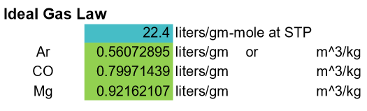
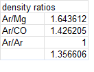
Figure 10. This is the gas density at STP for an Ideal Gas 29
Figure 11. The amount of Mg And CO produced. 29
Figure 14. Motive Gas Conditions 30
Figure 15. The Gases Combine 31
Figure 16. The Heat Balance 31
Figure 18. Cooling by Adiabatic Expansion 32
Modified Permanente Configuration 32
Figure 19. Permanente 2 Configuration 33
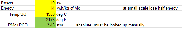
Figure 20. Furnace conditions 33
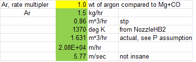
Figure 22. Argon assumptions 34
Figure 24. Gas rate assumption 34
Figure 26. Average velocity 35
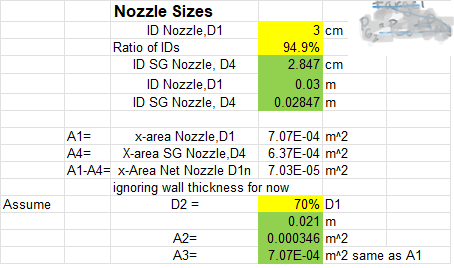
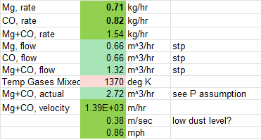
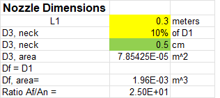
Figure 27. Nozzle dimensions 35
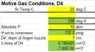
Figure 28. Motive gas conditions 35
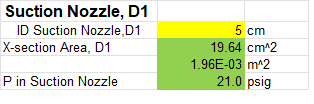
Figure 29. Suction gas conditions 35
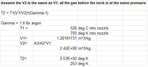
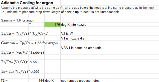
Figure 30. Adiabatic cooling for Argon. 36
Introduction to Process Development Reality, and Tools 37
Figure 31. Typical Steps in Process Development 37
Using the Permanente II Process to Produce Other Metals 38
Table 1. Metals most suited for the Permanente II Process 38
H2 Production from Methane via Molten Salt (pilot plant) 39
Figure 32 - Conceptual Reactor for Hydrogen Production Process 39
Figure 33 - Hydrogen and Carbon Black Production PFS 41
In order to build and transform the domestic critical supply of magnesium, one potentially fruitful approach is to use modern technology to improve the unit operations of older processes that were limited by the technology available when they were used. One such process is the Permanente Plant in the United States, which was successfully operated during WWII. In the war against Japan, the Permanente Metals Corporation, later known as Kaiser Aluminum & Chemical Corporation, built a magnesium plant that enabled the “burning of Japan.” The U.S., in this plant, made powdered magnesium based on a carbothermal process patented by F. J. Hansgirg (Patent #2,527,724). Coupled with modern technology, this proven technology provides a stepping stone for the U.S. to make low-cost magnesium again and dominate world production. Until my eighteenth birthday, I am willing to use my 60-ish years of experience in extractive metallurgy and 30-ish years in magnesium to help make this happen.
Basics of Carbothermal Magnesium Production
The potential of magnesium has been well documented. Could Telsa learn to make the frames for EV from magnesium if it was available and affordable in the United States?
Where My Life Intersected with Magnesium
In 1995, I was chosen as the lead process engineer for Fluor for the Australian Magnesium Company’s electrolytic magnesium process. In 2024, I am helping implement the same process with some improvements in India. The complexity of the Australian version of this process amazed me, and it set in motion a lifetime effort to find simpler methods. I would like to take credit for how simple the Indian entrepreneur has made this process, but it is his brilliance, not mine, that has gone to the essence of his new simpler electrolytic process to make magnesium.
Back to the past. After China lowered the price of magnesium to kill the funding of the Australian commercial facility, I was introduced to the original version of the” Laval nozzle carbothermal magnesium process” and worked to scale the process up with limited success. I built an extensive computer model for the carbothermal process, which predicted an operating cost 20 to 50% lower than any other method, with the cost of power being the most important cost variable. In addition, the model estimated the carbothermal process would produce much less CO2 than the Pidgeon Process used by the Chinese. However, there were some challenges to be overcome.
Back to the Basics
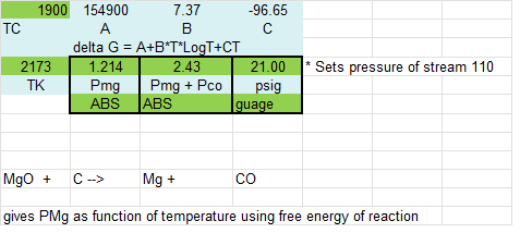
In the carbothermal process, magnesium oxide concentrate is reacted with coke at a high temperature, typically in a submerged arc electric arc furnace around 1800 to 2000oC, to produce carbon monoxide and magnesium gas.
MgO(s) + C(s) → Mg(g) + CO(g)
The two gases are then cooled rapidly, ideally in a fraction of a second, to recover the magnesium as a liquid or solid and to avoid the back-reaction. Simple in concept, very difficult in practice.
This challenge was overcome in a commercial plant by Permanente Metals in 1941. They made magnesium powder for the war effort. The CO and Mg were cooled by mixing them with natural gas. Baghouses removed the resulting magnesium powder. Downstream, the filtered natural gas and CO were returned to a power plant to make electricity. However, the cooling method employed frequently produced pyrophoric magnesium particles. Plants were also operated in Swansea, Wales, and Konan, Korea, based on a similar approach by the Austro-American Magnesite Corporation. This carbothermal process was discontinued because of the production of pyrophoric magnesium by these gas-quench condensers and several related deaths.
However, no one would argue that there are now technological solutions/alternatives for all of the challenges experienced in Permanente-type plants. More advanced technologies exist to cool and capture the magnesium particles.
A Closer Look at the Permanente Process
In the Permanente process, the product gases from the reaction, the CO and Mg(g), had to be cooled in a fraction of a second to about 200oC to prevent the reaction from reversing. Henry J. Kaiser, a famous American industrialist, built the plant that converted 80% of the MgO in the feed to magnesium; however, a pyrophoric powder was produced, and additional magnesium was lost to fires in the baghouses.
A rather straight upgrade of the Permanente Process would result in modern technology much superior to the original Permanente Process or to the Pidgeon Process currently used by China to make 90% of the magnesium used in the world today. The first upgrade would be to replace the baghouse with a properly engineered scrubber that uses oxygen-free, moisture-free mineral oil. This alone will result in a process that is superior to the original Permanente Process and the Pidgeon Process based on historical data from the Kaiser Plant. An amazingly simple and proven method for America to get back into the business of making magnesium.
The second upgrade would be to replace the nozzle used in the Permanente Process. In the original process, a hole was made in the graphite crucible to let the furnace gases escape. A cone was placed facing into this hole to fan the furnace gases into flowing natural gas. The cone was cooled with oil and scrapped periodically to remove the build-up of dust and any unreacted MgO. Whereas this simple nozzle worked, it is not even as sophisticated as the Laval nozzle used by CSIRO in Australia. In fact, nozzles called ejector nozzles, or sometimes eductor nozzles, have been designed to pull gases out of tanks, furnaces and other confined spaces. The obvious type of nozzle to use in the Permanente II is therefore the ejector nozzle, also discussed below.
This new version of the Permanente Process using an ejector nozzle is known as Permanente II Process in this report, or simply Permanente II. A test stand could be built in about a year that would enable the following to be demonstrated:
Can the performance of the Permanente Process be duplicated or exceeded when a ejector nozzle is used to pull Mg and CO from the furnace?
What is the impact on magnesium recovery of the ratio of motive gas to furnace gas (suction gas)?
Can an ejector nozzle, Figure 1, (with its four components: (1)the motive chest, (2) the converging/diverging motive nozzle, (3) the suction chamber, (4) the diffuser) ) be optimized to more efficiently cool the Mg and CO and prevent the back reaction than with the simple nozzles of the original Permanente design?
How much more efficient will the Permanente II be due to the CO being removed from the motive gas before recirculating it?
Can the fines produced by Permanente II be collected safely with modern technology? High-temperature ceramic filters and high-pressure mineral oil scrubbers will be tested to verify that both methods can safely collect magnesium fines. Relative performance, including pressure drop, cycle times, and ease of operation, will be rated for both the original Permanente Process and Permanente II.
The Laval Nozzle and the Carbothermal Process
Two groups, one backed by Jean-Raymond Boulle and another group backed by CSIRO, called MagnsonicTM, used a lavelle nozzle to cool the CO and Mg produced by the carbothermic reaction. Bench-scale reactors operating for hours demonstrated 100% recovery of the magnesium and promised to revolutionize the magnesium industry (and several others, for that matter). (Because of confidential agreements, discussion will be restricted to the results achieved and published by CSIRO.)
CSIRO’S MAGSONICTM PROCESS used Lavelle nozzles in Australia to cool the magnesium and carbon monoxide gases and successfully made magnesium in the years from 2003 to 2008. I understand they have new investors and are attempting to build a larger pilot plant in 2023. They claim, “MagSonic™ produces magnesium metal using up to 80 percent less energy and producing up to 60 percent less carbon dioxide emissions than the Pidgeon process.” They also have a project to produce magnesium as a by-product of desalination using their process.
In this technology, Figure 1, a vacuum is used to pull Mg and CO gases from a high-temperature furnace near atmospheric pressure through a Lavelle nozzle. Gases first pass into a converging section of the nozzle, which increases the pressure of the gas as it approaches the smallest diameter of the nozzle, called the neck or throat, before it expands into the diverging section of the nozzle, where it cools. In the process of expanding the gas, the heat energy of the gas is converted into kinetic energy, i.e., the velocity of the gas accelerates, typically to supersonic velocities.
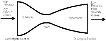
This rapid expansion causes near-instantaneous cooling of the gas. A typical time for cooling is about ⅕ of a second, although operational conditions of the nozzle vary widely.
Ideally, the magnesium solids or liquid goes down the center of the nozzle and is collected on a cooled target (or, in theory, in a scrubber) where the kinetic energy is converted back into heat energy; the carbon monoxide goes around the outside diameter of the nozzle and passes out of the system. However, in the CSIRO runs, solids built up after a few hours of operation near the exit of the nozzle. Eventually, the build-up became sufficient to interfere with the operation of the nozzle. CSIRO has several patents trying to avoid this problem (unconvincingly).
We propose leapfrogging from the Laval vacuum nozzles to a new technology that uses positive-pressure eductor nozzles and some unique motive gases and condensers. Meanwhile, CSIRO continues to try to make their MagsonicTM Technology reliable. Their greatest challenge will be to make it economically competitive since the costs associated with maintaining a hard vacuum, on which their process depends, are not small, nor is it easy to maintain stable conditions required for process control in this system. First, there are fluctuations in furnace pressure depending on the feed rate, its composition and variations in furnace temperature. The vacuum pump that creates the pressure drop across the nozzle is typically two or more unit operations downstream of nozzle. The“collection device” to capture the magnesium is typically the first unit operation. The second unit operation is typically a scrubber, or baghouse, or some other device to make sure particulates that pass through the magnesium collection device do not go out into the atmosphere. Condensers and/or cooling devices may be required on this line to make sure the temperature going into the vacuum pump is not excessive. Although the goal is to have stable operation of these devices, almost any change in these devices affects the pressure drop and gas velocities across the nozzle. In addition, a 15 psig pressure differential from the furnace to the vacuum pump across two to three unit operations is insufficient to maintain stable conditions across the nozzle, or the rest of the process for that matter.
Metallurgical Viability, Inc. first published the “Torpedo” Process on an internet blog in 2016. It has evolved and refined the process several times since then, and renamed it Permanente II. In this document, two variations of the process are presented. One named “the Ultra-low-Cost Permanente II” Process and the other is named the “Ulra-Green Permanente II Process.” In Europe, the market is favorable for Ultra-Green. The market is for Low-Cost and Urgent in “Texas” and with the U.S. Military reshoring initiatives.
There are a lot of moving parts to developing technology. Since I was first shown the Laval vacuum nozzle process in Scotland in 1995 by Marius, I believed that nozzle technologies could have huge economic potential and would long ago have been adopted in the U.S. Metals Industry of the 1980s. Moving to a positive-pressure ejector nozzle enables the stabilization of process conditions in front of and inside the nozzle. First, the pressure drop across the nozzle is not restricted to 15 psi; the upper limit of pressure is dictated by economics and the pressure drop across the nozzle can be controlled independently, within reason, of the conditions in the downstream unit operations as will be discussed in more detail in the next section and when discussing the two options presented here.
Let it be noted that many other tasks remain to be done before a commercial operation can be built around this ejector technology, such as acquiring feedstock, licensing supporting technology, permitting, and in some cases, upgrading feedstocks. All of this is doable either independently or by many international companies, both engineering companies and operating companies in the metals field, once they understand the capabilities of this ejector technology. Based on conversations with Peter O’Rourke, the U.S. military is interested in promoting both the R&D and production of magnesium in America.
The core nozzle technology is the same in the Ultra-Green or the Ultra-Low cost. The flowsheets, process conditions, and process control strategy varies significantly with these two approaches. Starting with what Henry Kaiser did fifty years ago as the “base case” it is simply a matter of some good engineering to modernize the proven Permanente process for making magnesium to the Permanente II process.
In my 57 years in extractive metallurgy, I have never seen a process, like Permanente II, that could have such an impact be so straight forward and ready for commercialization. Where is the Henry Kaiser of 2024?
Introducing an Ejector (Eductor) Nozzle and a Few Other Important Changes
In Figure 2, an eductor nozzle is shown. While this technology, discussed in more detail later, is critical for the Permanente II Process, the process selected to go around the nozzle is equally critical for its economic success.
CSIRO’s Magsonic Process demonstrated that Mg could be condensed and separated from the CO gas using a lavelle nozzle with minimal back reaction occurring. For a process to work well over extended time periods, stable process conditions must be maintained. Transient changes from one process state to another often result in unsuitable conditions for the desired reactions to occur. For whatever reason, magnesium oxide and carbon deposits tend to build up in the exit end of the nozzle, which eventually stops the process. The process, as practiced by CSIRO, was limited by the pressure drop across the nozzle, from essentially one atmosphere of gas in the furnace (PCO + PMg) to the vacuum level that was maintained at the exit end of the nozzle. The pressure drop, in turn, limited the amount and rate of cooling of the gases and controlled the amount of cooling. The present approach hypothesizes that at least part of the time, stable conditions are not maintained across the nozzle in the Magsonic Process. These unstable conditions contribute to poor cooling and back reaction in part of the nozzle. Therefore, in the present approach, compressors are used to maintain higher and more stable pressures not only across the nozzle but in the unit operations in front of and following the nozzle. This strategy comes with a cost, but the first goal is to achieve a robust nozzle, and second to optimize the economics.
Using an eductor nozzle circumvents the problems encountered in the Magsonic Process by allowing large pressure differentials across the nozzle, sheathing the process gases inside an envelope of the motive gas, and allowing more aggressive cooling from the larger pressure drop (as needed) and from mixing the process gas with a relatively cool motive gas. (There are several disadvantages of the ejector, discussed later. ) In essence, this combines the best of the Permanente Process and the MagSonic Process. The selection of the appropriate motive gas also allows a great deal of flexibility in the unit operations downstream of the nozzle, as will be discussed and demonstrated with the two examples under consideration, Ultra-Green and Ultra-Low-Cost.
A few generalizations about the operation of the eductor. There is a great deal more flexibility with this system than is first apparent. For instance, I assumed the motive gas would always be at a higher pressure and velocity compared to the process gas, which is often called the suction gas. In this scenario, kinetic energy is transferred from the motive gas to the suction gas, causing the suction gas to be pulled along with the motive gas. The velocity of the combined gases is calculated by using the conservation of momentum principle. However, calculations show that because the process gas is much hotter, more expanded, that it is relatively easy to set process conditions where the actual volume of gases is greater in the suction side of the nozzle than the motive side of the nozzle. In short, there is a great deal of flexibility in how the system is operated both to achieve robustness and efficiency.
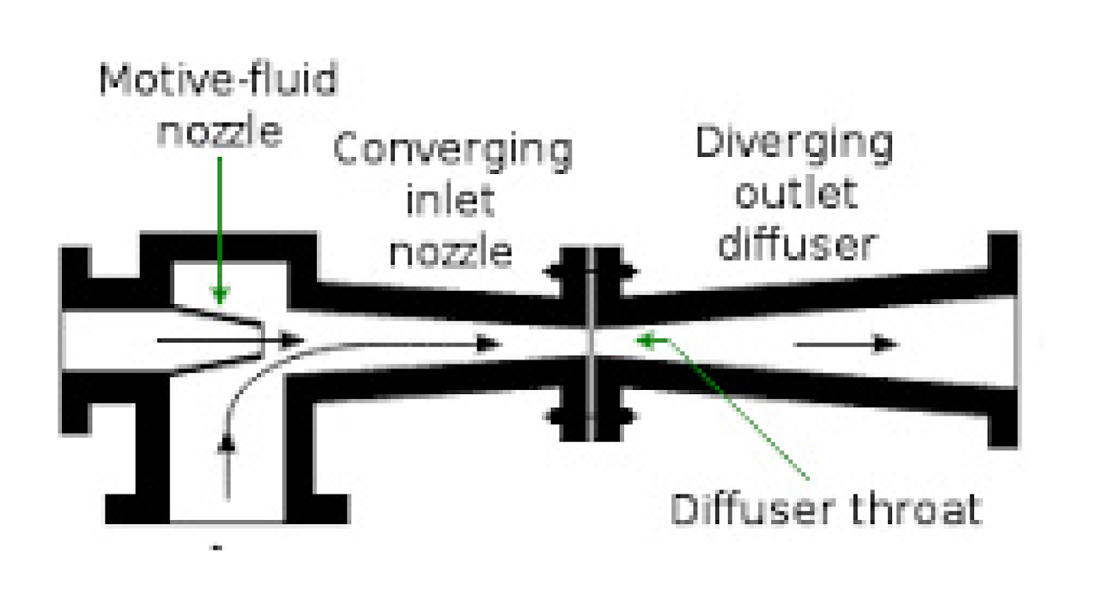
The combined gases are pulled into the converging inlet nozzle, where the gases are compressed through the diffuser throat and then expanded in the diverging outlet diffuser, where they are cooled by expansion. The relative diameter change from the diffuser throat to the diffuser outlet can be used with the ideal gas law to approximate the amount of cooling done by expanding the gas. This cooling, combined with the sensible heat cooling from mixing the motive gas with the process gas (the suction gas) gives an estimate of the total amount of cooling of the CO and Mg that can be achieved by this approach. The time of cooling can be estimated by the time the gases spend in the nozzle, given their velocities.
Disadvantages of the Ejector
The chief disadvantage of the ejector does not occur in the nozzle but downstream where more gases with fines must be handled. This disadvantage has the most consequence in the scrubber, the device used to separate the fines, or perhaps droplets, from the gases. There are three factors that impact the nozzle size and the downstream scrubber size:
The ratio of the motive gas volume to the suction gas (process gas) volume
The pressure at the exit of the nozzle
The pressure ratio, Pin/Pout , and not to be overlooked,
The pressure and temperature of the suction gas and the motive gas.
It should be noted that the pressure and temperature of the suction gas depends on:
The availability and the reactivity of reactants,
The temperature of the reactants/furnace,
The power input into the furnace,
And if additional motive gas is directed and at what pressure, into the furnace to increase the pressure and stability of the suction gas.
The last variable, the pressure of the suction gas, and the pressure of the furnace, needs a little clarification. If the temperature of the furnace is raised to 2000oC, the pressure in the furnace reaches about 5 atm (absolute) or about 4 atm (gauge), or about 60 psig. However, this can be further increased by directing some of the motive gas into the furnace at the same pressure, or different pressure than the motive gas going into the nozzle; whether this is advisable or not, or when it is advisable, is another issue.
Advantages of an Ejector System
The stability of the nozzle flow is maintained by a mechanical pump maintaining a constant pressure of the motive gas at the inlet of the nozzle. Additionally, gas, usually the motive gas, can be injected into the furnace to maintain a constant pressure of the suction gas to offset any instability in the feed system. Ideally, the amount of this additional gas is small (<<10%) but along with the motive gas, it creates a steady state pressure drop and flow rate across the nozzle. Magnesium gas is cooled to small magnesium particles which are carried out of the nozzle. When motive gas quantity>>suction gas quantity, then the maximum stability of the nozzle is achieved. One could imagine if there was no suction gas, the nozzle would be completely stable indefinitely; but of course, with no production of magnesium. As suction gas increases relative to motive gas, the particle loading of the gas increases (especially over the back half of the nozzle), and the stability of the nozzle becomes more difficult to maintain. Instabilities in the feed system and the downstream scrubber have increasingly larger effects on the nozzle. To somewhat oversimplify a complex system, the goal of the R&D is to minimize the motive gas flow while maintaining stable flow across the nozzle. Selection of downstream equipment probably has more impact on this nozzle stability than any other choice we make in engineering this system.
In other words, the critical requirement for the success of the eductor system is that the pressure at the exit of the nozzle must remain low and constant. As critical for the success of the system as the nozzle is the solid/gas separation device selected to remove the fine magnesium particles from a rapidly moving gas. Some companies specialize in such systems. In all likelihood, the system will have two or more devices in a series configuration, such as a venturi scrubber coupled with a cyclone that has a filter on its exit. To make the system foolproof, this system must be oversized; to make magnesium production economical, it must be minimized. Engineering at it’s finest.
In all likelihood, a scrubbing media, a liquid phase, will be introduced to help remove the particles from the gas phase and to wet the particles for subsequent handling.
The nozzle/scrubber combination is the heart of the system. Most of the shortcomings of the “Permanente Process” revolved around particle/gas separation. Baghouses used in the Permanente system are difficult to operate even in much simpler systems and by their very nature, cycle between a low-pressure condition when they may work properly and a high-pressure condition where they become ineffective. In contrast, ejector venturi scrubbers and particulate matter scrubbers, in general, are capable when properly engineered of steady-state flow where solids are removed at the same rate they are added. The LaValle-type nozzle in the backend of the ejector, not only prevents the back reaction, it also lowers the gas temperatures making material selection and thermal stress problems in the scrubber more manageable. It simultaneously lowers the actual volume of gases because of the lower temperature while simultaneously increasing the velocity of those gases. All necessary data for those designing the scrubber system.
Nozzle Test Stand
In setting up our system, we want an oversized scrubber system that allows us to test a variety of gas flow rates and nozzle configurations without being limited by the scrubber system. We also need a high-pressure graphite furnace, similar to that of AVS, Inc., Figure 3, that enables the production of Mg and CO where PCO + PMg >> 1 atm. The furnace can generate pressures up to 2500 psig and temperatures up to 3,000 oC. The first generation of the Permanente II Process will not use the full potential of the AVS, Inc. furnace. Different commercial objectives can be met by carefully selecting motive gases and the downstream unit operations.
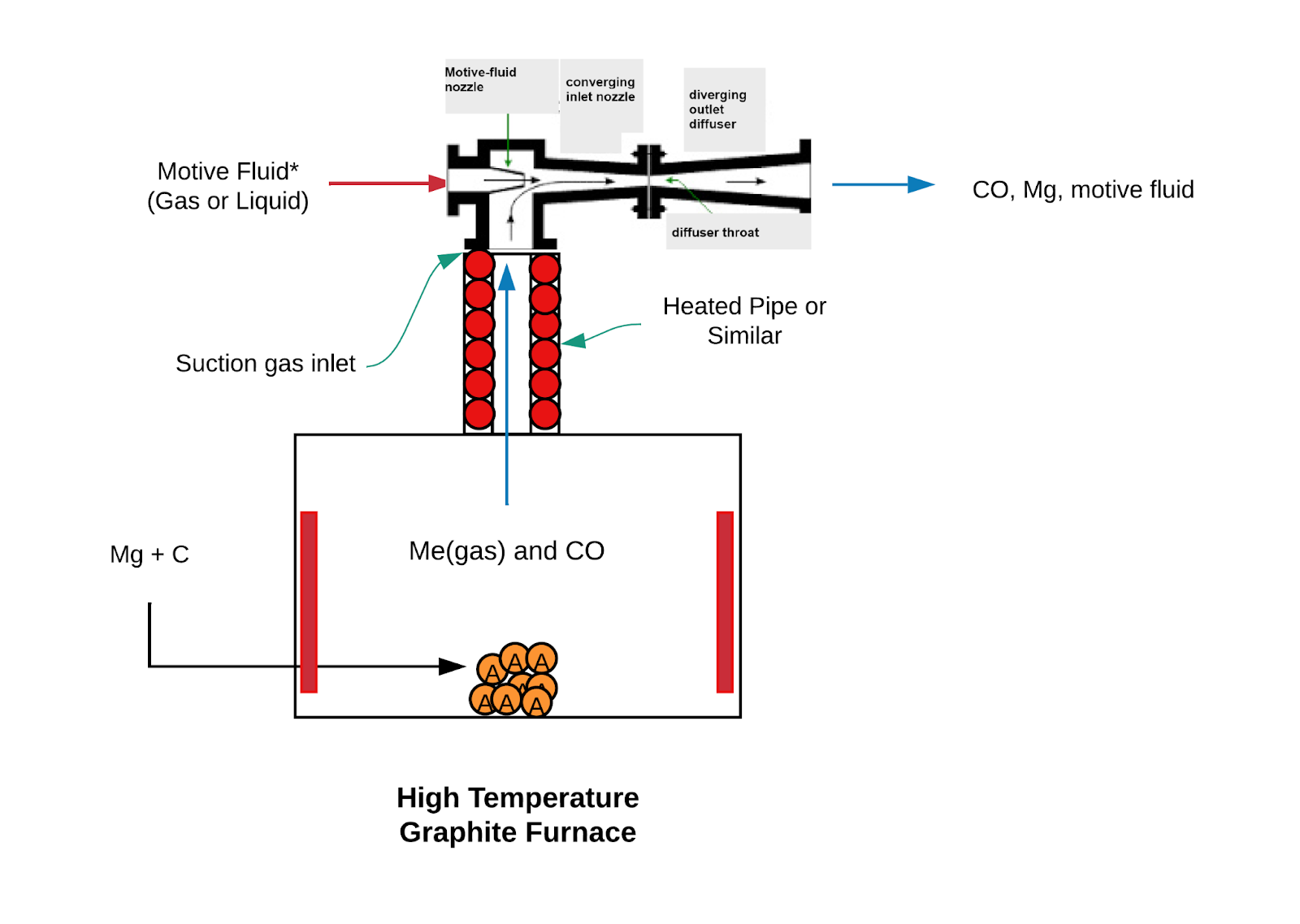
Using the eductor nozzle and a furnace capable of high pressures and temperatures offers much improvement over how the process was carried out at the Permanente Metals plant during the war, which only used sensible gas cooling, or the Magsonic Process, which only used the capabilities “vacuum” nozzles.
In addition, as will be demonstrated, the positive pressure downstream of the nozzle makes additional processing of the combined gases easier, including allowing the use of condensers that require a pressure gradient and unit operations that remove the carbon monoxide from the motive gas. Removing CO from the mixed gas stream allows the motive gas to be recirculated, which in turn allows gases such as argon to be used as motive gas further simplifying the process, as will be shown.
In this paper, we are going to combine the technology with several other unit operations to create a process that will produce magnesium consistent with the current goals of society. In the first case, we will emphasize making a profitable process that is uncompromising on the environmental front (or at least one school of thought) and on the second process, we will make a process that attempts to maximize profits while still improving the environmental aspects of making magnesium compared to the Chinese with the Pidgeon Process.
A quick look at the mathematics of the ejector nozzle is shown in the appendix and I hope to soon be able to link an Excel spreadsheet to document.
Beyond the Basics with Carbo-Thermal Magnesium
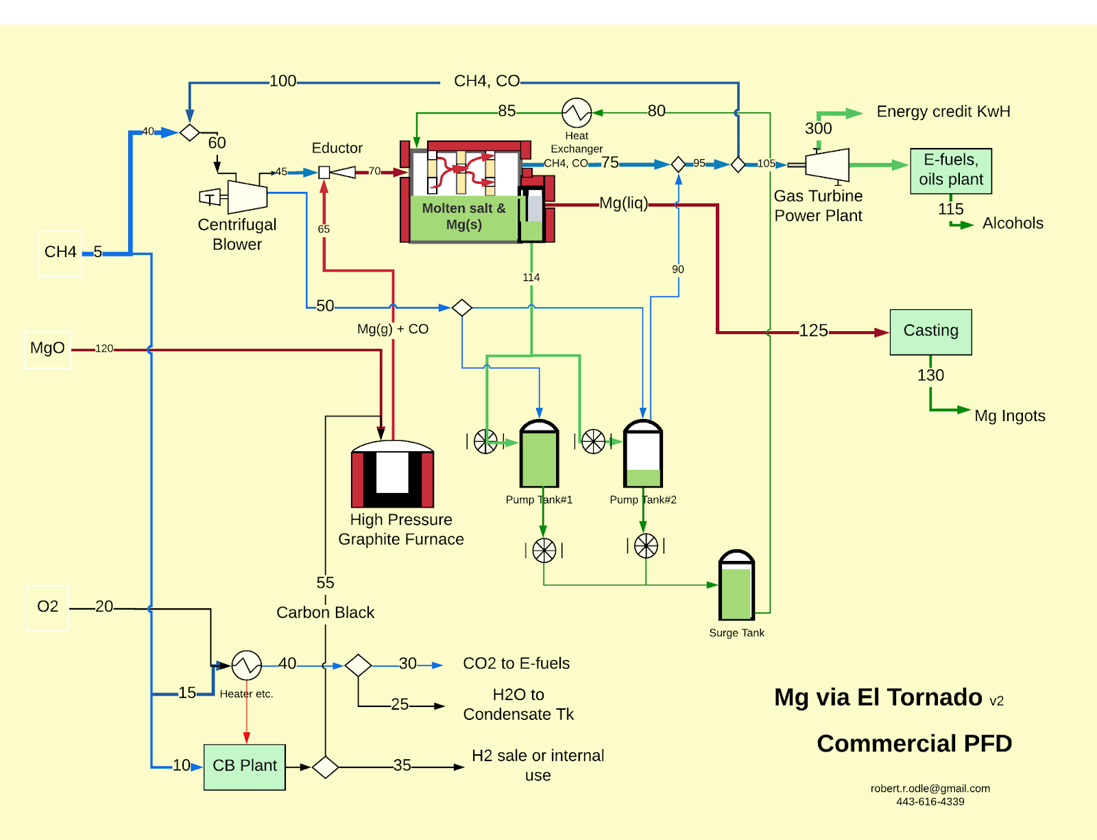
In the full commercialization of positive-pressure nozzle processes, there are many unit operations both in front of behind the nozzle, Figure 4.
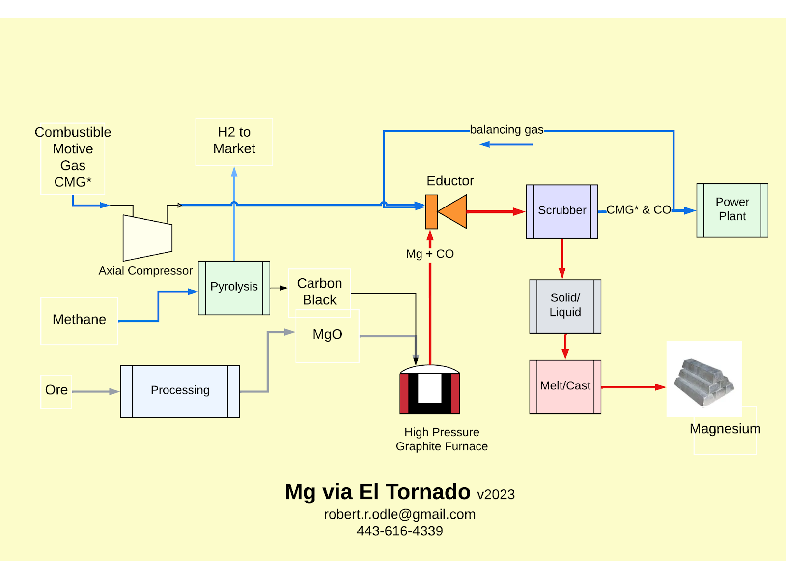
Upstream of the nozzle, compressors or blowers are required to move the motive gas into the eductor, a supply of carbon black and magnesium oxide must be purchased or preferably made from raw materials. Such processes are already in commercial production. Technology can either be licensed or duplicated with due respect for IP.
Downstream of the nozzle, the magnesium particles or droplets must be removed from the gas stream by scrubbing, and the motive gas has to be used for fuel and/or recycled after CO removal. Various technologies for accomplishing these steps are described herein. As a disclaimer, the reader should be advised that not all key information required to make these flowsheets viable is necessarily included. Most, however, are either available in the technical literature or from my experiences in 20 years of R&D in magnesium.
Adapting The Permanente II Process to Your Priorities:
There are many ways to implement the Permanente II Process. We will discuss two categories of processes for implementing carbothermal magnesium: 1) Processes that result in an ultra-green process for making magnesium, and 2) processes that result in an ultra-low-cost process for making magnesium. All processes presented here assume carbon black, from the thermal decomposition of methane, either licensed or purchased from those already operating such plants. Other carbon sources can be used such as various forms of coke. Magnesium oxide (MgO) is assumed as the feed source. Making and/or obtaining MgO is a side project discussed in the appendix.
Ultra-Green Permanente II Processes with No COx Released.
Permanente II Processes Producing Ultra-Low Cost Magnesium
Ultra-Green Magnesium Production
Ultra-Green Magnesium Production is defined as magnesium metal production where no carbon products are put into the air and that is capable of using renewable electricity either directly or indirectly through the grid.
An Ultra-Green Permanente II Process, PFS#1
In Figure 5, the Permanente II Process when an inert gas is used as the motive gas is shown. Since most inert gases, argon in this example, are expensive, economics dictates they must be recirculated to minimize usage. Hence, by necessity, CO must be removed before the argon gas is recirculated to maintain viable thermodynamics in the eductor nozzle.
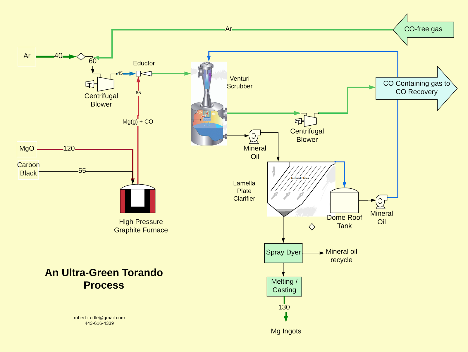
As can be seen in this process flow diagram, this is an incredibly simple flowsheet for making magnesium compared to any flowsheet the author knows of. The simplicity of the process will be reflected in the cost.
As before, the motive gas, Ar, is used to pull Mg and CO gas from a positive-pressure furnace into the eductor and downstream into a venturi scrubber in this example. The scrubber removes the magnesium particles or droplets (depending on the operating temperature) from the gas stream. In this example, mineral oil is used to scrub the magnesium from the gas stream. The magnesium particles are removed from the mineral oil with a lamella plate clarifier to produce a magnesium sludge, which is dumped into a heated distillation tank. Mineral oil left in the sludge is removed by gentle heating under a mild vacuum and returned to the process. The magnesium is dropped into a furnace for melting and casting. Some very fine magnesium particles will be circulated from the lamella clarifier back to the scrubber to provide nucleation sites for the magnesium condensing in the scrubber.
An alternative is to take the sludge from the lamella settler or the scrubber directly and use a spray dryer to separate the magnesium powders from the mineral oil. Such devices can be controlled precisely, even to the point of deliberately leaving a residual amount of oil on the magnesium particles to reduce their flammability. The magnesium particles would be dropped directly into a stirred magnesium bath to facilitate their melting and subsequent casting. The more manually intensive process with the distillation tank described above could be used until enough sludge is made to allow vendor testing of a spray dryer to properly design it (TBD).
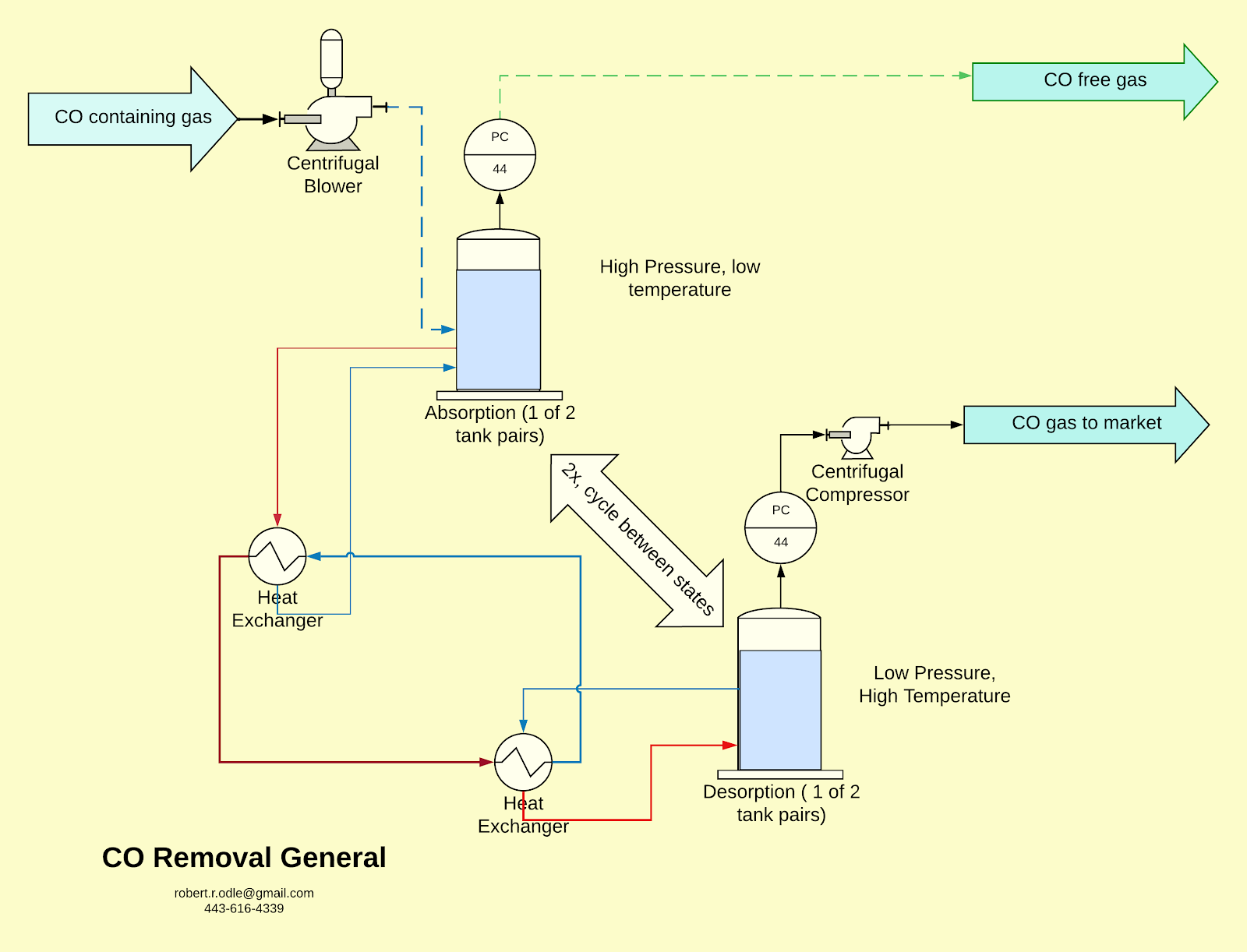
Before recirculating the argon, the carbon monoxide can be removed by several solvents using typical pressure swing absorption technology, Figure 17. For example, expired Patent 2,519,284 Method of Absorbing Carbon Monoxide is one of several patents/processes to recover CO from a process gas. The argon passes through this solvent and can be compressed and recycled to the front of the process. The CO can used in the shift reaction to make H2 or by more complex processes into alcohols. There are people in the business making efuels, our CO would be a desirable feedstock for over-the-fence plants.
A company like Kingston Process Metallurgy could be used to optimize conditions for CO recovery on the lab scale, and then we could install a small system to demonstrate that the CO can be recovered and the argon recycled to the front of the process in our pilot plant.
This can either be purchased commercially or a good chemical engineer can use the information in the Appendix and/or the literature to implement this process. This decision is primarily driven by project timing; in-house implementation will probably be more cost-effective, and purchasing the technology will allow the project to progress faster.
The CO recovered can be marketed directly or used to make hydrogen or lubricants. CO can also be burnt as a fuel, and the heat is used in the process and/or over the fence. How the carbon monoxide is used/sold is a marketing and sales decision for the project.
Processes Producing Ultra-Low-Cost Magnesium
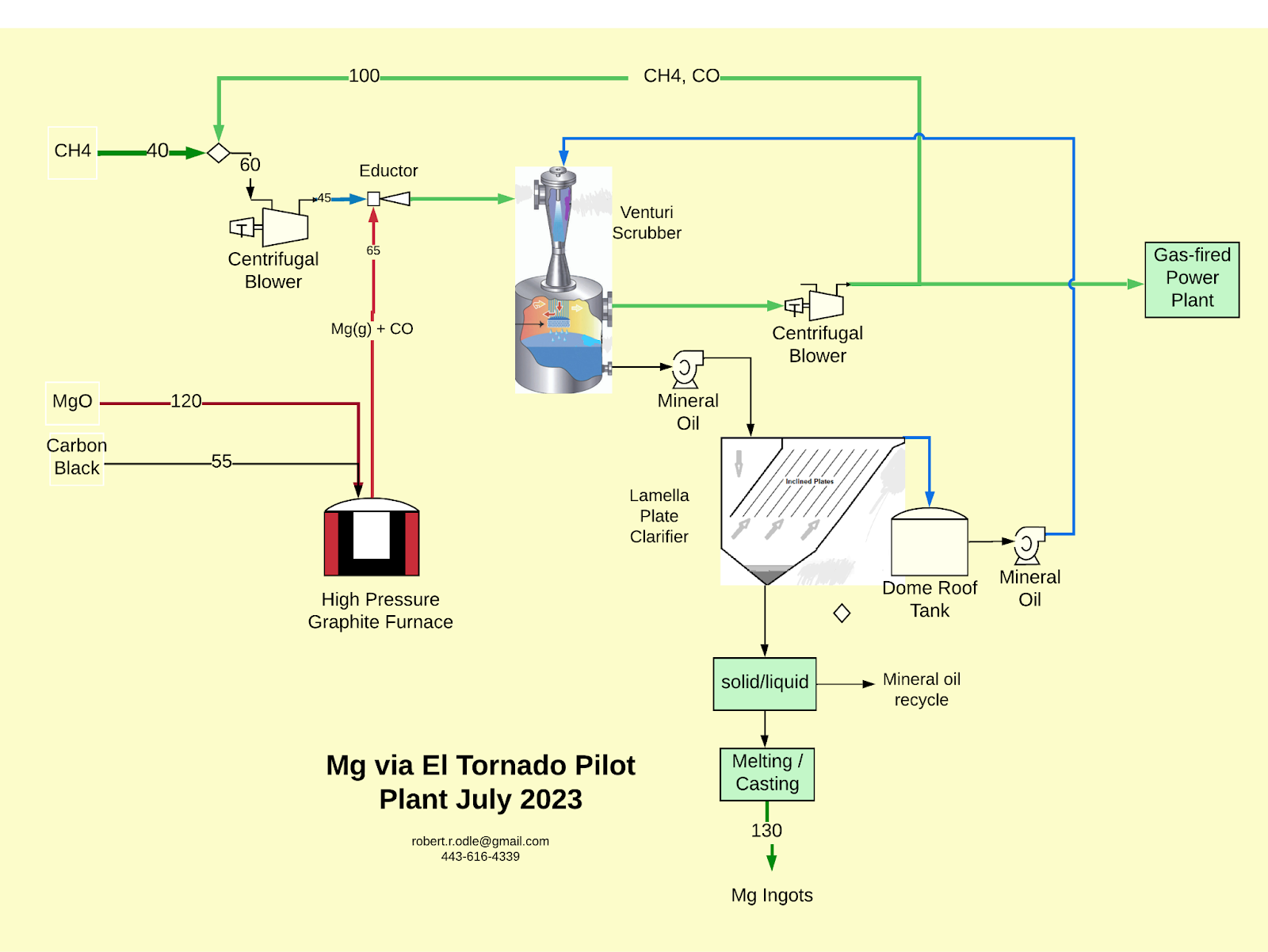
Ultra-Low-Cost Magnesium Production can be produced on a facility that has a dedicated power plant operating on purchased methane and the gas by-products of the magnesium production. Sometimes referred to as engine power plant solutions, these plants are designed to work on methane mixed with other fuels while providing flexible turn-up/turn-down capabilities.
An Ultra-Low-Cost Magnesium Flowsheet, PFS#3
This flowsheet uses the eductor/lavalle nozzle combo to condense magnesium solids and then capture them in a commercial scrubber, Figure 7. The sludge from the scrubber is settled in a commercial settler which produces a thickened sludge of magnesium powder in mineral oil. It also produces mineral oil with a small amount of magnesium fines that serve as nucleation sites for magnesium particles in the scrubber.
In initial phase of the pilot plant, the thickened sludge can be dropped into a covered electric furnace, which is heated and under a slight vacuum to remove the mineral oil. After the mineral oil is removed, the powder is covered with an argon cover gas, and the temperature is increased to melt the magnesium. The magnesium is manually cast into ingots from the “tipping furnace.”
After we can reliably produce mineral oil containing magnesium fines, we can ship these wetted fines to a vendor to select a pilot-scale spray dryer. Fines from the spray dryer will be emptied into a small furnace to make ingots manually.
An Ultra-Low-Cost Magnesium Flowsheet, PFS#4
The flowsheet, Figure 8, has the same unit operations as PFS#3; however, molten salt is used to scrub magnesium vapors from the gas phase and to collect either magnesium fines or magnesium liquid. The difficulty of dealing with molten salts should not be underestimated.
The less dense molten salts have LiCl as a major component, but their melting points are typically more than 600 to 700oC. These salts all the collection of magnesium from the bottom of the settler. However, selecting materials that can tolerate the potential corrosion when moist air gets into the salt and simultaneously handle being exposed to molten magnesium is not a trivial task. Lower molten point fused salts make material selection easier but necessitates collecting the magnesium as a sludge (salt plus magnesium) and then melting this in a side chamber. It's doable but difficult.
A fused salt system has some energy-saving advantages over the mineral oil system, at least on paper, but getting such a system designed and working is more difficult than getting the ejector/nozzle working and is probably not justified for a pilot plant. If the mineral oil system, or some similar organic, works well, it may be difficult to justify a fused salt system for a commercial system.
Other Torpedo Processes
There are other carbothermal magnesium processes, for example:
There is a process flowsheet for producing magnesium-aluminum alloys like AZ91 where excess heat in the circuit is used to melt aluminum for the alloy and an intermediate Mg-Al alloy is used to collect the magnesium vapors at a temperature below 500oC lowering operating costs and saving significant capital costs.
There is a Torpedo process flowsheet that allows the simultaneous production of magnesium and calcium from dolomite, significantly reducing the cost of production of each metal.
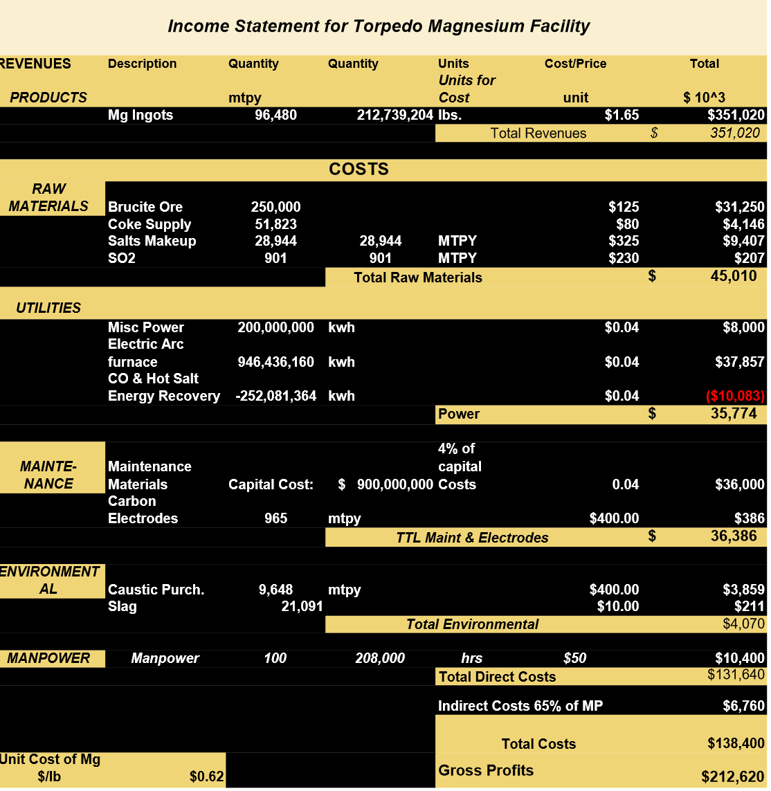
Cost Structure of Permanente II Process Producing Ultra-Low Cost Magnesium
Appendix
Potential Feed Stocks for Magnesium Production Using the Permanente II Process
The simplest Process Flowsheet for the Permanente II Process when magnesium production is the goal is achieved when a relatively high-grade magnesium oxide and carbon black are used as the feedstock. The reduction reaction at or above 1800oC produces gaseous products at a positive pressure.
The Permanente II process uses nozzle technology to cool the gases rapidly, convert the magnesium gas to liquid or solid magnesium, and facilitate its separation from the carbon monoxide (CO). The CO is burnt to CO2 to provide some energy for the process; the CO2 is used for e-fuels or sequestered in concrete or similar. The entire process operates above atmospheric pressure, including the condenser.
The authors have proposed a process to make carbon black from a partial decomposition of methane in molten salts, presented later. This carbon black combined with a source of MgO, discussed next, makes the application of the Permanente II Process very straightforward compared to most commercial options for making magnesium. It is the author’s opinion that testing the Permanente II Process on carbon black and MgO is the most efficient method to demonstrate the physical operation of the nozzle without the distractions of answering all the hypothetical questions associated with selecting of feedstock for a project of unknown size in an unknown location. The most relevant questions involve impurities in those feedstocks; however, all these questions relate to the cost of removing or eliminating them, not whether they keep the process from meeting the magnesium specification (ASTM 9980A). A possible exception to this statement is nickel, for which can not easily be removed.
In general, the process can also use Brucite (Mg(OH)2) after drying or Magnesite (MgCO3) after calcining. The process can also use dolomite (based on a theoretical study from China) with two different approaches. In both approaches, the dolomite is first calcined to dolime. In the first approach, the dolomitic lime is mixed with carbon and some flux(sand) and charged directly to an electric arc furnace. As before, magnesium gas and carbon monoxide are produced and separated by the nozzle technology. In addition, a calcium silicate slag is produced that can be used as an additive for cement manufacturing. The downside of this approach is that a lot of material is melted, which does not produce magnesium.
In the second approach, the dolime is leached with MgCl2 and/or HCl to remove most of the CaO from the dolime as calcium chloride (CaCl2), which is then converted to gypsum (CaSO4.2H2O) (wallboard) with sulfuric acid while recycling the MgCl2/HCl to leach more dolime. MgO is produced by this leaching and used directly in the Permanente II Process. This method has more potential environmental challenges but probably has higher capital cost than the first alternative with dolomite but with lower operating costs.
MgO can also be produced from magnesium silicate ores (eg., olivine) by hydrometallurgy while co-producing a silicate product. This hydrometallurgical process and the dolomite hydrometallurgical option are significant projects in their own right and should be managed accordingly. The author’s opinion is that this technology should be developed after the carbothermal process has been shown to be robust.
In short, the methods of producing an acceptable feedstock for the Permanente II Process vary from simple to complex, each with its nuances and economics.
The commercial options for feedstock are many, especially if upgrading feedstock by hydrometallurgical options is included. The nozzle development could easily be distracted by these discussions.
Mathematics of Nozzle
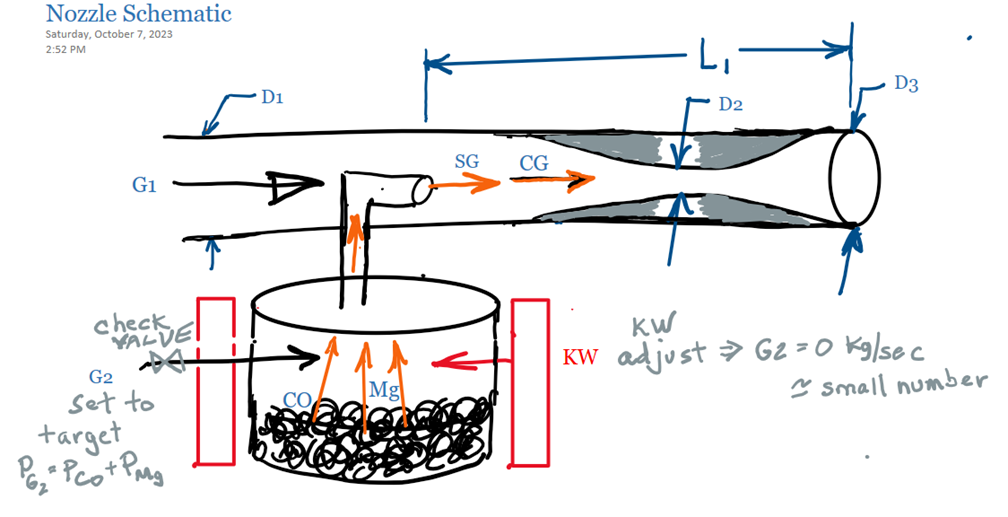
Nozzle Configurations for Motive and Suction Gases
Our starting place is the configuration used on the Permanente Process where Mg and CO are injected into a flowing stream of gas. This was a robust process that produced a lot of magnesium fines captured in oil. How do we enhance this process, and combine it with the cooling of a lavelle nozzle, all without losing the robustness of the process? (see calculations in Spreadsheet under Models)
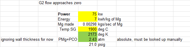
A large furnace will approach the theoretical value of about 5 to 7 kwh of energy depending on the actual composition of reactants per kg of magnesium produced. However, on a small pilot plant, the losses of energy to the surroundings are significant and this value must be determined by experimentation for each experimental setup. These calculations demonstrate the concept and give approximate predictions.
It is assumed more than enough quality reactants are present and a relatively uniform temperature in the furnace and throughout the bed of the reactants. At these elevated temperatures, the theoretical predictions are close to the actual conditions. A VBA subroutine has been set up to do these calculations after the temperature is put in manually.
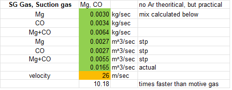
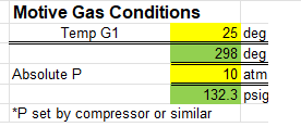
The first challenge becomes apparent with this configuration. The motive gas is at room temperature, pressurized by a compressor, and is very dense compared to the furnace gas which is expanded from being at an elevated temperature and relatively low pressure. The amount of motive gas must be increased excessively, 5 times the furnace gas, to get comparable volumes of the motive gas and furnace gas interacting with each other. Although somewhat arbitrary, having near equal volumes of the two gases and similar properties, mostly density, will facilitate the mixing of the two gases and the exchange of heat energy between the two gases. Large gradients of temperature and density is not conducive to a stable process. This example will be continued for its educational value before the configuration is modified in the second example.
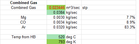
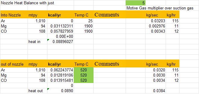
With the argon flow at five times the rate by weight of the furnace gases, the combined temperature of the furnace and argon gas is predicted to be 520 degrees centigrade before the LaValle part of the nozzle is reached.
While the above prediction is favorable with regard to adequate cooling of the magnesium, the amount of argon that must be compressed and subsequently handled downstream is excessive from an economic viewpoint. Also, the gas velocities are high which in practice would result in pressure drops down the length of the nozzle and much less gas coming out the end than predicted by these calculations.
The author believes it is desirable to adjust the configuration in a way that the quantities, densities, and velocities of the gases are more equal before the gases are merged together. This is more a pragmatic approach driven by experience dealing with systems that dramatically different conditions over short distances, ie., steep gradients in unit operations, that do not lead to stable operation.
Modified Permanente Configuration
What appears as a relatively small change in the schematic of the nozzle configuration is accompanied by two changes in assumptions that have a significant impact on the calculations and hopefully corresponding changes in the performance of the nozzle configuration.
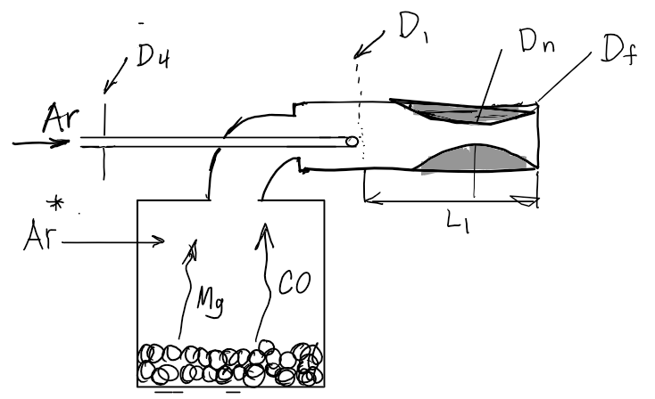
The small relative size of the motive gas nozzle, which will contain argon that has been compressed by mechanical means, implies that the furnace gases will not be significantly cooled because of the relatively small heat transfer area and because heat is being transferred by radiation from the furnace and furnace nozzle walls to the motive gas nozzle. However, the impact on the motive gas is more significant. The gas will expand, and its density drop as its temperature increases. The goal is to have the motive gas close to the temperature of the furnace gas as the argon leaves the motive gas nozzle. A compressor will set the pressure of the argon at the beginning of the nozzle, and the pressure of the argon at the open end of the nozzle will be close to the furnace in the furnace and the furnace nozzle. If excessive gradients exist, the size of the nozzles will be adjusted. (Subsequent calculations may also improve our ability to achieve this goal.)
The goal is to have a relatively small amount of argon injected into the furnace to have a stable pressure, on the order of 10% or less of the total gas flow from the furnace will be argon. In this iteration of the calculation, the amount of argon injected into the furnace is assumed to be small, approaching zero.
Introduction to Process Development Reality, and Tools
Building and commissioning a chemical or metallurgical plant or pilot plant, the following steps can be taken with various degrees of rigor to ensure an efficient developmental process and a viable facility, or not.

While each of these steps will not be discussed in detail in this proposal, a rigorous developmental procedure will be followed to ensure the work is done efficiently and a viable, functioning pilot plant is the end result.
Using the Permanente II Process to Produce Other Metals
The Permanente II Process is a nozzle-based technology that enables the carbothermal production of metals reducible by carbon at elevated temperatures and pressures. Carbothermal processes can be more cost-effective when operated at elevated temperatures that generate pressures above atmospheric. However, injecting inert or nonreactive gases into the furnace to maintain a positive pressure can also be used, as discussed later in the economic tradeoffs.
The ultimate goal is to operate at pressures significantly higher than atmospheric to enable the specific capacities of the furnace system from 10 to 100 times that achievable by systems operated under vacuum. The higher operating pressures and the low cost of the reductant results in a significant reduction in capital and operating costs compared to comparable technologies operating under vacuum or near atmospheric pressures with more expensive reductants.
The Permanente II Process applies to metals that are a gas at the reduction temperature. For example, the metals in bold in Table 1 are ideally suited to the carbothermal process:
.
*Complicated. SiO, Si, or SiC can form depending on operating conditions.
H2 Production from Methane via Molten Salt (pilot plant)
It is the author’s opinion that hydrogen would make an ideal gas for the eductor nozzle
In the technical literature, there have been several papers indicating that hydrogen can be made by the thermal decomposition of methane (a known scientific fact). Of relevance, there are several companies advocating bubbling methane through molten metals to facilitate its decomposition. The experience we are acquiring in handling and managing molten salts can be leveraged into using molten salts in systems that require high-temperature heat transfer including the production of hydrogen from decomposing methane which, at its heart, is a heat-transfer challenge. A conceptual reactor for this process is shown in Figure x.
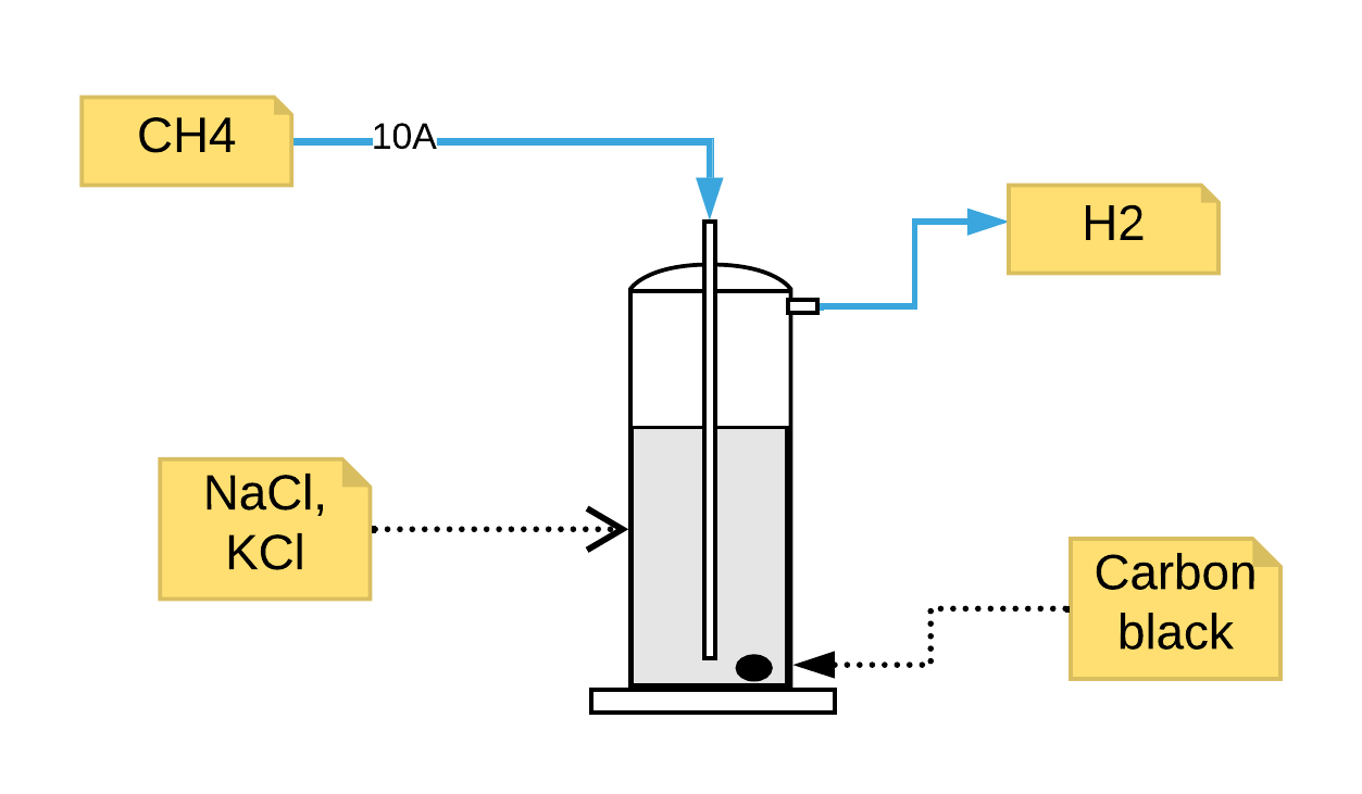
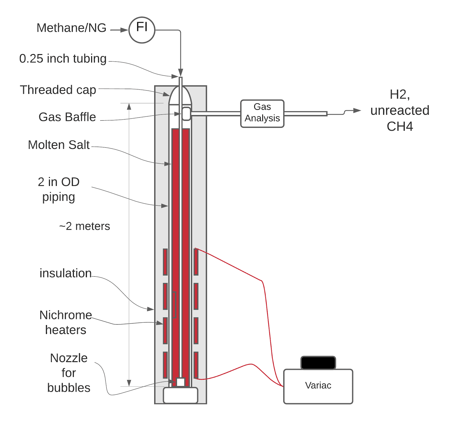
In a commercial Permanente II Process, the two most promising motive gases are methane or hydrogen. The amount of carbon monoxide produced by the carbothermal magnesium process contains a great deal of energy that must be used wisely for the full economic potential of the process to be realized. The carbon monoxide will become mixed with the motive gas in the nozzle. The use of hydrogen for the Permanente II Process is ideal. A low-cost source for that hydrogen can be obtained by passing methane through molten salts as shown in its simplest form in Figure x. An instrumented version of such a system is shown above and right. Data from this system could be used to design a commercial unit, see next page.
The size and residence time of the methane bubbles, the temperature, and the pressure of the system determine the percentage of methane that will be converted to hydrogen. These parameters determine the length of piping required to make a commercial system along with the desired grade of the hydrogen product. For use in the Permanente II Process, a grade of 90% H2 will be more than adequate.
The second product of this system is carbon black of very high purity. The particle size of this carbon black will depend on operating conditions. A higher operating temperature is expected to result in coarser particles, and the presence of nucleating surface (other carbon black particles or added catalytic surfaces) will also tend to increase particle size and the efficiency of the conversion. Whereas the particle size is not overly critical when they are used in the Permanente II Process, the size could be critical if the carbon black is sold in other markets, say tire production or in plastics, to reduce infrared degradation.
The molten salt used in this system will not be the same as in the condenser/settler. A lower-cost, lower melting point, and denser molten salt will be chosen. The impact of the salt on the performance of the system is expected to be of secondary importance compared to the operating conditions discussed above.
Carbon black is possibly carcinogenic, and suitable personal protective equipment must be used when handling carbon black. Figure x shows the PFS of this process.
A conceptual design of a system to make hydrogen and carbon black from methane for the Permanente II Process is shown above. For the Permanente II Process, complete conversion of the methane to hydrogen is not required.
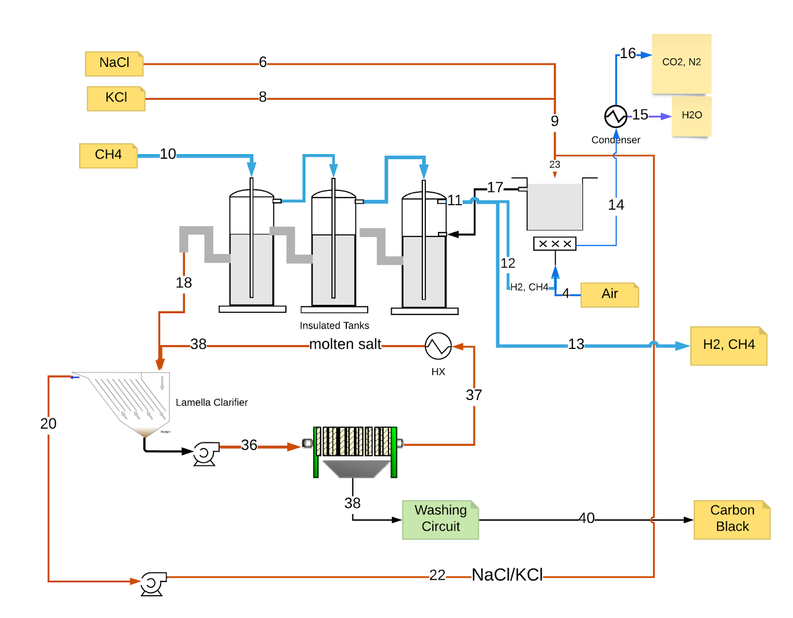
In the proposed system, methane flows counter-current to a flow of molten salt contained in vertical pipes (tanks). As the methane flows through each column, more of it is converted to hydrogen. After the gas passes through the molten salt contained in all the columns, most it goes to the Permanente II Process for use as a motive gas in the nozzles used there. A small amount of the product gas is used to maintain the temperature of the molten salt. During start-up from idle, all the product gas will be used to heat up the salt from the idle temperature to the operating temperature.
The carbon black content of the molten salt becomes higher as it passes through the system. The molten salt overflows the last tank (relative to the molten salt) into a clarifier to allow most of the carbon black to settle. The overflow is pumped back to the molten salt preheat tank along with very fine carbon black that did not settle. The carbon black fines that settle to the bottom of the clarifier are pumped through ceramic filters to remove the carbon black. (Such technology will be very similar to removing MgO from our molten salts.) The carbon black produced will be sent to a washing and drying circuit before being used internally or sold. If no water discharge is our policy, then an evaporator and crystallizer circuit will be required to recover the salts and water for reuse. Otherwise, a simple wastewater treatment plant could be implemented.
This facility requires us to continue developing our expertise in using molten salts for industrial heat management. This expertise will be used for molten salt nuclear reactors, heat transfer in pyrometallurgical and hydrometallurgical operations, and in the chemical and petrochemical industries. It is the expertise we must develop to be viable given the condenser/settler technology we have chosen to use in our magnesium circuits; capitalizing on that expertise is a lucrative opportunity in many areas.
The one fact that makes the production of hydrogen and carbon black via the decomposition of methane in molten salts less risky is this: the economics of the process only depends weakly on the % of methane that is converted into hydrogen. In a typical commercial facility making hydrogen gas for sale, the tolerance of methane as an impurity in the product hydrogen gas is very low. In our case, 50% conversion could be viable (modeling needed). Our requirement is to get enough carbon black out of the circuit that will make our target level of magnesium. Hydrogen can be sold as a by-product of our plant.
Subscribe to:
Posts (Atom)